Content Menu
● What Excessive Pressure Loss Means in a GAC System
● The Two Performance Factors That Must Be Balanced
● Why Some GAC Media Causes High Pressure Loss
>> Fine Particle Content Is Too High
>> The Effective Size Is Too Small
>> Particle-Size Distribution Is Too Broad
>> Suspended Solids Are Accumulating in the Bed
>> The Operating Flow Is Above Design Conditions
>> Bed Depth or Vessel Design Is Incorrect
● Clean-Bed Loss Versus Fouling Loss
● How to Specify GAC for Lower Pressure Loss
● Backwashing: A Performance Control, Not a Routine Guess
● A Practical Diagnostic Example
● Choosing a Reliable GAC Partner
● Frequently Asked Questions
>> What is considered excessive pressure loss in a GAC filter?
>> Does smaller GAC always create higher pressure loss?
>> Can activated carbon fines cause pressure loss?
>> Why does GAC pressure loss increase after several weeks?
>> Will a coarser GAC solve high differential pressure?
>> How often should a GAC bed be backwashed?
● References
Granular activated carbon (GAC) is selected for adsorption, but its hydraulic behavior can determine whether a treatment system operates reliably. Excessive pressure loss across a GAC bed can reduce flow, raise pumping energy, shorten filter runs, complicate backwashing, and limit the actual treatment capacity of a vessel.
For water treatment, air purification, chemical processing, food production, and pharmaceutical applications, the problem is rarely caused by one factor alone. GAC particle size, particle-size distribution, dust content, bed depth, inlet water quality, operating flow, and vessel design all interact. A carbon grade with excellent adsorption capacity may still be the wrong choice if it creates an unmanageable pressure drop under real operating conditions.
At Guangdong Tongke Activated Carbon Co., Ltd., we view activated carbon selection as a balance between adsorption performance and hydraulic efficiency. The goal is not simply to supply carbon with a high iodine number or large surface area. The goal is to deliver a GAC media specification that matches the contaminant, flow rate, contact time, pressure allowance, and regeneration or replacement plan of the customer's process.
What Excessive Pressure Loss Means in a GAC System
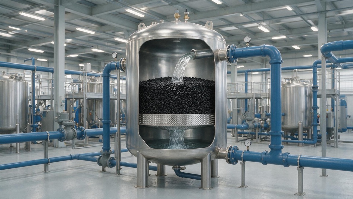
Pressure loss, also called pressure drop or headloss, is the reduction in pressure between the inlet and outlet of a carbon vessel. It occurs because water, air, gas, or another fluid must pass through the empty spaces between carbon particles.
A clean and properly designed GAC bed will create a predictable pressure loss. The concern begins when the measured pressure loss is much higher than the expected clean-bed value or rises rapidly during operation.
Pressure loss affects more than pumping cost. It can reduce available flow, create uneven flow distribution, increase bypass risk, impair product quality, and force unplanned shutdowns.
In a water-treatment contactor, a rising differential pressure may indicate that suspended solids are accumulating at the top of the bed or deeper within it. In an air or gas purification unit, it may point to fine particles, moisture-related agglomeration, channel restriction, or an unsuitable carbon mesh size.
The right question is therefore not, "Does the GAC have pressure loss?" Every packed bed does. The better question is: "Is the pressure loss appropriate for this fluid, flow condition, and treatment objective?"
The Two Performance Factors That Must Be Balanced
The central comparison is between GAC adsorption performance and GAC hydraulic resistance. These factors are related, but they are not identical.
Smaller carbon particles often provide faster adsorption kinetics because contaminants travel a shorter distance to reach internal pores. However, smaller particles also reduce the open void space between granules. This can increase resistance to flow.
Larger particles usually allow easier flow and lower clean-bed pressure loss. But if the particles are too large for the contaminant and required contact time, adsorption may be slower and breakthrough may occur earlier.
| Media characteristic | Potential adsorption effect | Potential hydraulic effect |
| Smaller effective size | Faster mass transfer and more accessible external surface | Higher pressure loss |
| Larger effective size | May require more contact time for difficult contaminants | Lower pressure loss |
| Narrow particle-size range | More predictable bed behavior and backwash expansion | More stable hydraulic performance |
| Excess fines | May offer short-term adsorption surface | Rapid pressure-loss increase and fouling risk |
| High hardness | Better resistance to abrasion and attrition | Helps limit fine generation over time |
| Correct bed depth | Supports required contact time and capacity | Adds predictable resistance that must be designed for |
The best GAC is not automatically the finest or the most adsorptive grade. It is the grade that delivers the required removal performance while maintaining an acceptable pressure drop throughout the operating cycle.
Why Some GAC Media Causes High Pressure Loss
Fine Particle Content Is Too High
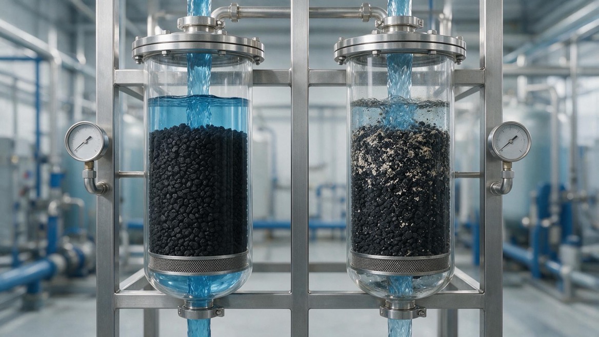
The most common reason for excessive GAC pressure loss is an elevated level of fines. Fines are small carbon particles generated during crushing, screening, transport, filling, abrasion, or repeated backwashing.
Even a limited amount of fine material can migrate into void spaces between larger particles. As those spaces narrow, fluid velocity through the remaining channels increases and the pressure drop rises.
Dust control should therefore be part of the media specification, not an afterthought. Buyers should ask for particle-size distribution data, abrasion resistance information where relevant, and a clear washing or dedusting procedure before shipment.
A carbon bed may initially appear acceptable, then develop high resistance soon after startup because fines were not fully removed before commissioning. This is especially common when a vessel is filled quickly, when initial rinsing is insufficient, or when the system has no effective backwash sequence.
The Effective Size Is Too Small
Effective size describes the particle diameter associated with the smaller end of the usable particle-size distribution. It strongly influences both contact efficiency and pressure loss.
A smaller effective size creates narrower flow passages. At the same flow rate, fluid must move faster through those passages, creating more friction. This effect becomes more significant as flow rises.
For example, a fine mesh GAC may be attractive for rapid removal of certain dissolved organics, odors, or low-concentration contaminants. However, using that same fine grade in a high-flow industrial water system without adequate vessel area can result in a high initial pressure loss and an even faster increase as solids accumulate.
Selection discipline matters more than a generic mesh recommendation. The carbon grade should be chosen after reviewing fluid viscosity, temperature, loading rate, target compound, influent solids, and allowable pressure differential.
Particle-Size Distribution Is Too Broad
Two GAC products may have the same nominal mesh designation but behave differently in service. One may have a well-controlled, uniform particle-size distribution. The other may contain too many undersize particles, oversized pieces, or inconsistent screening fractions.
A broad distribution allows smaller particles to settle into gaps between larger particles. This creates a denser bed structure and lowers permeability.
A controlled distribution improves bed uniformity and makes hydraulic behavior easier to predict. It also supports more consistent bed expansion during backwashing.
Nominal mesh alone is not enough for technical purchasing. A supplier should be able to provide sieve analysis data and explain the product's effective size and uniformity characteristics.
Suspended Solids Are Accumulating in the Bed
GAC beds often act as both adsorbers and physical filters. This can be useful, but it also means that incoming turbidity, corrosion products, biological solids, oil droplets, scale, or process debris can collect in the upper bed.
As the solids layer develops, pressure loss increases. Eventually, the problem is no longer primarily about carbon quality. It becomes a pretreatment and operating-control issue.
The U.S. Environmental Protection Agency notes that carbon contactors require backwash and surface-wash provisions to prevent excessive headloss from solids accumulation and surface clogging.
Common upstream contributors include:
- High turbidity or poor clarification
- Iron and manganese precipitates
- Biofilm or microbial growth
- Activated sludge carryover in wastewater treatment
- Oil, grease, and surfactant contamination
- Cartridge-filter failure or bypass
- Pipe scale released during flow changes
Pretreatment often produces the largest improvement. A properly sized sediment filter, multimedia filter, clarification step, oil-removal stage, or oxidation-and-filtration process can substantially extend GAC run length.
The Operating Flow Is Above Design Conditions
Pressure loss does not increase in a simple one-to-one relationship with flow. When flow rises, friction through the packed bed can increase sharply.
A contactor designed for one flow rate may develop excessive differential pressure if it is later used for peak production, emergency throughput, or a changed process load. Higher temperature and lower viscosity may reduce hydraulic resistance somewhat, while colder and more viscous fluids can raise it.
Actual flow data should be reviewed rather than relying on average flow alone. Systems should be checked at normal, peak, and upset operating conditions.
Where higher throughput is unavoidable, practical options include increasing vessel diameter, using parallel vessels, selecting a coarser GAC grade where treatment allows, or reducing upstream solids loading.
Bed Depth or Vessel Design Is Incorrect
Bed depth provides adsorption contact time and capacity, but it also adds resistance. A deeper bed is not automatically better if the vessel cross-sectional area is too small.
Poor internal design can make the situation worse. Inadequate inlet distribution may direct most flow to one section of the bed. An unsuitable underdrain can cause uneven collection, local compaction, media carryover, or ineffective backwashing.
Hydraulic distribution should be evaluated as carefully as carbon specifications. A good media grade cannot compensate for an undersized vessel, poor distributor design, blocked laterals, or inadequate freeboard.
Clean-Bed Loss Versus Fouling Loss
A practical way to diagnose a GAC problem is to separate the initial clean-bed pressure loss from the pressure increase that occurs during operation.
| Observation | Likely cause | Recommended response |
| High pressure loss immediately after startup | Fine carbon, undersized media, incorrect flow, poor initial rinsing | Verify mesh, sieve data, flow rate, and commissioning procedure |
| Gradual increase over days or weeks | Suspended solids accumulation, biological growth, scale | Review pretreatment, inspect influent quality, optimize backwash |
| Sudden pressure-loss increase | Filter failure, process upset, pipe debris, oil carryover | Investigate upstream event and isolate the source |
| Uneven pressure behavior between vessels | Distributor issue, different media loading, channeling, valve problem | Compare flow, bed depth, internals, and carbon batches |
| High pressure loss after backwash | Incorrect backwash rate, media stratification, residual fines | Review expansion rate, water temperature, and rinse sequence |
A clean-bed differential-pressure baseline should be recorded immediately after startup and after each effective backwash. This baseline gives operators a reference point for identifying abnormal fouling.
EPA case data from a two-stage GAC system showed that solids removal within carbon columns contributed to measurable headloss buildup between backwash cycles, reinforcing the importance of tracking both influent solids and differential pressure.
How to Specify GAC for Lower Pressure Loss
A purchasing specification should focus on the application, not only on standard laboratory indicators. Iodine number, molasses number, ash, moisture, and hardness remain important, but they do not independently predict pressure loss in a working contactor.
Use the following specification process.
1. Define the fluid: Identify whether the application uses water, wastewater, humid air, dry gas, solvent vapor, syrup, beverage liquid, pharmaceutical process water, or another stream.
2. Confirm the contaminant objective: State the target compounds, influent concentration, required outlet level, and expected loading variation.
3. Set the operating envelope: Provide minimum, normal, and peak flow; operating temperature; viscosity where relevant; and maximum allowable pressure drop.
4. Review upstream quality: Include turbidity, suspended solids, oil, biological matter, iron, manganese, and any chemical that may precipitate.
5. Select a suitable particle size: Balance adsorption kinetics with hydraulic capacity rather than selecting the smallest available grade.
6. Request particle-size data: Review sieve analysis, effective size, uniformity, and fine-particle limits.
7. Confirm mechanical durability: Select a carbon with suitable hardness and abrasion resistance for the expected handling and backwash conditions.
8. Validate vessel design: Check bed depth, service loading rate, distributor design, underdrain design, freeboard, and backwash expansion capability.
9. Establish acceptance criteria: Agree on clean-bed differential pressure, sampling points, startup flushing, and pressure-loss alarm limits.
Application-specific design prevents many costly errors. A GAC grade appropriate for a low-flow polishing unit may be unsuitable for a high-flow pretreatment contactor, even when both systems treat the same contaminant.
Backwashing: A Performance Control, Not a Routine Guess
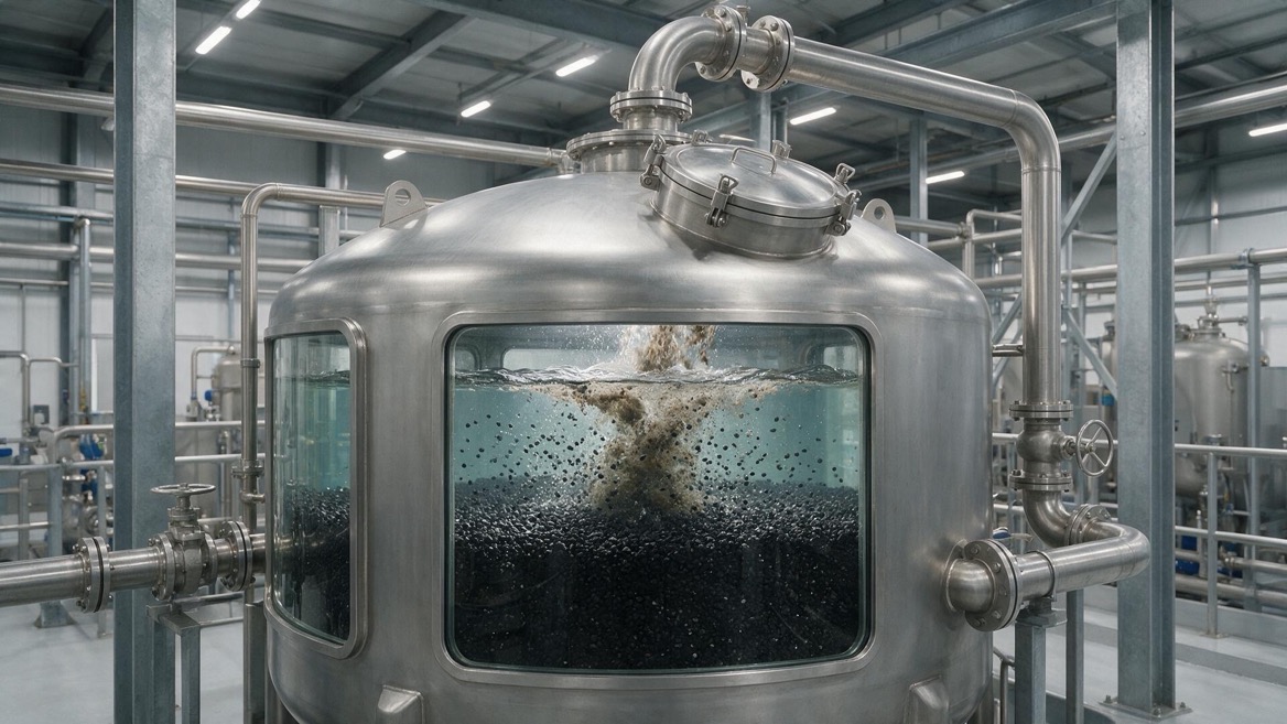
Backwashing removes collected solids, reclassifies the media bed, releases trapped air, and restores hydraulic capacity. But an overly aggressive backwash can cause carbon loss, media disturbance, or damage to fragile particles. An insufficient backwash may leave fines and solids in place.
Backwash flow must account for water temperature because bed expansion changes with temperature. The system also needs adequate freeboard so that expanded carbon does not escape the vessel.
Measured expansion is better than a fixed flow rule. Operators should confirm the actual bed expansion and observe backwash discharge until it becomes acceptably clear.
For a typical granular carbon grade, supplier technical documents commonly provide clean-bed pressure-drop curves and temperature-dependent bed-expansion guidance. These values are useful design references, but the final operating target should be verified with the actual carbon, vessel, and water quality in service.
A Practical Diagnostic Example
Consider a wastewater polishing unit that develops high differential pressure only two weeks after a new GAC charge. The initial assumption may be that the supplied carbon is too fine.
A structured review may show a different cause:
- The clean-bed pressure loss was acceptable after startup.
- The pressure increased only after high suspended-solids events upstream.
- Backwash flow was lower than required because the backwash pump was undersized.
- Solids remained trapped near the upper carbon bed.
- The carbon itself met its specified size distribution.
In this case, changing to a coarser GAC might reduce resistance temporarily, but it would not solve the root cause. Improving pretreatment and correcting the backwash system would protect both hydraulic performance and adsorption capacity.
Root-cause analysis avoids expensive media changes that do not address the real operational problem.
Choosing a Reliable GAC Partner
A dependable activated carbon supplier should help customers interpret performance as a complete system. The discussion should include carbon type, particle size, pressure-loss allowance, fluid quality, operating flow, vessel configuration, and maintenance strategy.
For industrial buyers, useful supplier support includes:
- Application-based grade recommendations
- Particle-size and quality-control documentation
- Custom mesh-size options
- Technical input for water, air, gas, food, chemical, and pharmaceutical systems
- Guidance on initial rinsing and backwashing
- Support for comparing virgin, reactivated, pelletized, and granular carbon options
Guangdong Tongke Activated Carbon Co., Ltd. supplies activated carbon solutions for global industrial applications and can help evaluate GAC media selection against both removal targets and hydraulic limits. Request a technical consultation with your process conditions, flow range, target contaminants, vessel dimensions, and current differential-pressure data to identify a suitable carbon specification.
Frequently Asked Questions
What is considered excessive pressure loss in a GAC filter?
It depends on the vessel design, fluid, flow rate, and available pump pressure. Excessive pressure loss is usually identified when the differential pressure exceeds the system's operating limit, reduces required flow, or rises much faster than the established clean-bed baseline.
Does smaller GAC always create higher pressure loss?
In general, smaller particles create more flow resistance because they form smaller void spaces. However, actual pressure loss also depends on particle-size distribution, bed depth, flow rate, fluid viscosity, fines content, and solids accumulation.
Can activated carbon fines cause pressure loss?
Yes. Fines can fill spaces between larger carbon particles, restrict flow, migrate downstream, and increase pressure drop. Proper screening, washing, loading, and commissioning are important for reducing this risk.
Why does GAC pressure loss increase after several weeks?
The most frequent cause is solids accumulation from the influent stream. Turbidity, biological matter, iron precipitates, scale, oil, and process debris can clog the bed. Inadequate backwashing can accelerate the increase.
Will a coarser GAC solve high differential pressure?
It may reduce clean-bed pressure loss, but it is not always the correct solution. If the main cause is upstream solids, biofouling, poor backwashing, excessive flow, or vessel-internal problems, the root cause must be corrected first.
How often should a GAC bed be backwashed?
Backwashing frequency should be based on differential pressure, flow performance, influent quality, and operating experience rather than an arbitrary calendar schedule. The backwash rate must be sufficient to expand and clean the bed without excessive media loss.
References
1. U.S. Environmental Protection Agency, "Carbon Adsorption," including operating provisions for backwash and surface wash to control headloss. [EPA source] [www3.epa]
2. U.S. Environmental Protection Agency, "Two-Stage Granular Activated Carbon Treatment," including observed initial headloss and headloss buildup during operational cycles. [EPA source] [nepis.epa]
3. Calgon Carbon, "FILTRASORB 200 Product Data Sheet," including effective-size data, clean-bed pressure-drop information, and startup backwash guidance. [Product data sheet] [calgoncarbon]
4. Water Quality Association, "Activated Carbon: Filtration, Contactor or Both?" including carbon contact-time and hydraulic-loading considerations. [Technical article] [wqa]
5. American Water Works Association, "B604: Granular Activated Carbon," a technical standard covering granular activated carbon used in water-treatment applications. [Standard page] [store.awwa]
6. Balanay, J. G., et al., "Determination of Pressure Drop Across Activated Carbon," research discussing how media density and structure influence pressure drop. [CDC publication] [stacks.cdc]


